Energy monitor
on Web Server
Frequently Asked Questions
Below are frequently asked questions. Let us know if you have not found the answer you were looking for ...
Questions? Please contact us
Contact us
A. LoWi (en ReMI)
-
1. How to monitor energy consumption if the meters are in the basement of the apartment?
Q: I live in a rooftop apartment on the fifth floor. The meters hang downstairs in the basement. I own solar panels. There is no way to run wiring upstairs.... Read moreQ: I live in a rooftop apartment on the fifth floor. The meters hang downstairs in the basement.
I own solar panels. There is no way to run wiring upstairs. Are there ways to monitor my consumption and control consumers in my apartment? Solution 1: Network over powerline with TP link:
Tested (3 phase installation) with this wifi over powerline from tp link and it seems to work anywayhttps://www.coolblue.be/nl/product/865806/tp-link-tl-wpa8635p-kit-wifi-1200-mbps-2-adapters.html
So TP link base module connect via RJ45 to the modem in the apartment, remote module place in the technical room where the digital meter is. Both WiFi networks have same IP range. Connect LoWi3/ReMI/ELAN in basement with TP link WiFi in technical room. Via the WiFi in the apartment surf to IP address LoWi/ReMI/ELAN to monitor consumption. Switching can be done with the ReMI/ELAN contacts in the technical room. Solution 2: A wired solution with the P1 extender:
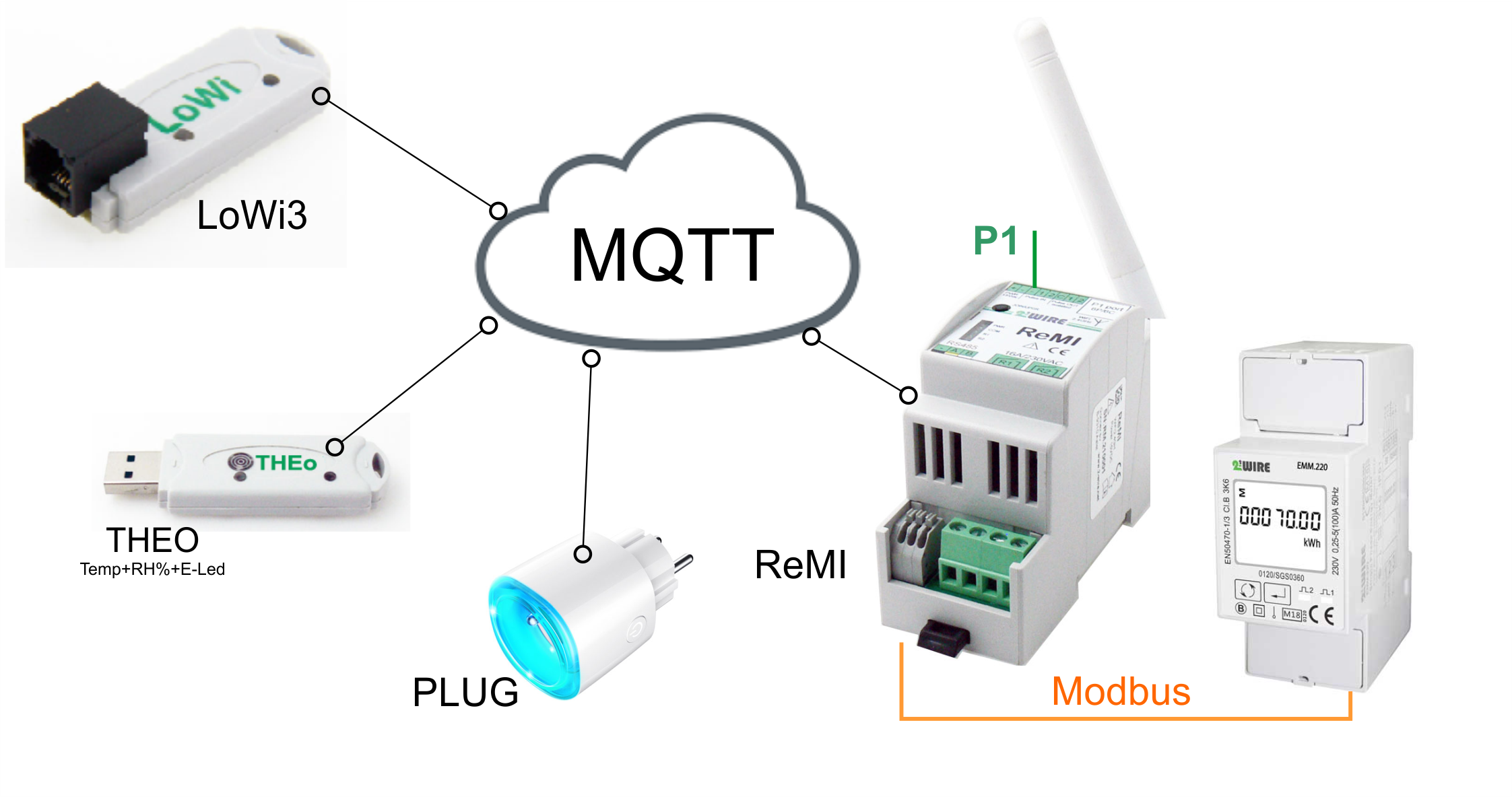
P1 with UTP cable extend into the range of the WiFi in the apartment. https://www.2-wire.net/product/p1-poort-extender/ Solution 3: 2-Wire webservers can be linked over the Internet (MQTT). The prerequisite is that there is a stable WiFi Internet connection at both (or more) locations. Here one can possibly use the TP link modem of solution 1. The measurement values from location 1 are then transmitted in real-time via Internet MQTT to location 2, location 3,…. and can then be monitored via any smartphone or tablet within the home network. Practical:- In the basement a LoWi3 module to read the digital meter, or else a ReMI module if, in addition to total consumption and injection from the digital meter, one wants to measure e.g. the yield of the inverter and e.g. consumption of the storage room.
- In the apartment a second ReMI if one wants smart switching, or a LoWi3 if one just wants to monitor
- Possibly a pair of smart-plugs to household appliances will monitor or switch.
The necessary modules
- – 1x LoWi3 + P1 adapter cable (power via USB) if no digital meter
- – 1x ReMI + power supply HDR-15-12 if no digital meter
- – 1x MQTT token
Solution 4: Place ReMI or ELAN in the apartment and measure total consumption/injection there not via P1 but with a Modbus meter on the supply cable.
P.S. Location 1 could also be your apartment in Spain which you want to monitor live consumption from home.
Location 3 is then possibly a WiFi smartplug on your caravan in the ardennes.
-
2. Remote access for LoWi, ReMI, ELAN with the APP LORE
The APP LORE provides remote access via MQTT to the LoWi3, ReMI and ELAN web server. However, you will need a license/token to the 2WIRE MQTT server. This license/Token (1... Read moreThe APP LORE provides remote access via MQTT to the LoWi3, ReMI and ELAN web server.
However, you will need a license/token to the 2WIRE MQTT server.
This license/Token (1 per location) can be ordered online at this website.
You can enter the MQTT token in the configuration page of the web server:1. in the setup web page, check ‘MQTT enable’,
2. Enter URL and Token:
url: mqtt.flespi.io token: exact64_characters_without-space_copy_otherwise_you_will_not_get_saturn_icon
3. Save with password “adminLOWI”/”adminREMI”/”adminELAN” ( and Saturn icon appears if MQTT is OK,
4. Check the firmware version (reverse date =>24.8.26.1) and upgrade if necessary,
5. Select your country code (NL Netherlands, BE Belgium, FR France, DK Denmark)
Download the zip file APP_LOREv1.html from the website: https://www.2-wire.net/html-app/ and copy the file to your PC.
Open the APP_LOREv1.html file with your web browser.
Select in the first input field an empty or existing line and click on EDIT button and enter name/MAC(exactly 12 characters) and your MQTT token(exactly 64 character) and click again on EDIT to save.
You will be taken directly to the dashboard page of your LoWi3, ReMI or ELAN webserver.
Layout is only available in dark mode and remote configuration is also not possible via this app. -
3. Important firmware update LoWi and REMI
With the introduction of the capacity tariff early this year, Belgian digital meters received a firmware update. In this update, the Belgian P1 protocol was extended to include data such... Read moreWith the introduction of the capacity tariff early this year, Belgian digital meters received a firmware update. In this update, the Belgian P1 protocol was extended to include data such as current, voltage, power separately for each phase, quarter power and a history of the highest monthly peaks. This additional data requires doubling the internal data buffer (especially with 3-stage installation) of the LoWi3 and ReMI module and this requires an upgrade.
LoWi upgrading can be done in several ways:(see also video at FAQ A)
- – Upgrade locally through the setup page:
In the setup page at UPGRADING select ‘START’ and confirm with ‘ adminLOWI ‘
– Upgrade remote via port-forwarding is possible only if you are logged in as administrator. (See FAQ section E) - – Manual upgrade via the switch on the online(WiFi+internet) LOWI stick:
Approx. 5 sec. press the LoWi switch until the LED is constantly lit in order to start the upgrade - – Automatic upgrade can be done by checking BETA in the setup page (See FAQ section A)
ReMI upgrading can be done in several ways: (see also at FAQ B)
- – Upgrade locally through the setup page:
- In the setup page at UPGRADING select ‘START’ and confirm with ‘ adminREMI ‘
- – Upgrade remote via port-forwarding is possible only if you are logged in as an administrator. (See FAQ section E)
- – Manual upgrade via the switch on the online(WiFi+internet) ReMI module:
Approx. 5 sec. press the ReMI switch until the LED lights steadily to start the upgrade - – Automatic upgrade can be done by checking BETA in the setup page (See FAQ section A)
- – Upgrade locally through the setup page:
-
4. How to make LoWi/ReMI upgrade automatically?
In the setup page of the LoWi and ReMI web server, you can check BETA* and then WITHOUT pressing SAVE immediately select START to upgrade to BETA. *See no BETA... Read moreIn the setup page of the LoWi and ReMI web server, you can check BETA* and then WITHOUT pressing SAVE immediately select START to upgrade to BETA.
*See no BETA mark then you have an older FW version and just need to upgrade first.
After a reload page, if the upgrade to BETA is successful, a blue check mark will indicate that it is active .
From now on, the LoWi/ReMI module will check for a newer version every night and upgrade on its own if necessary.
Returning can be done by unchecking BETA and then immediately selecting START WITHOUT pressing SAVE to disable BETA.
-
5. Setting up manual meter in LoWi3
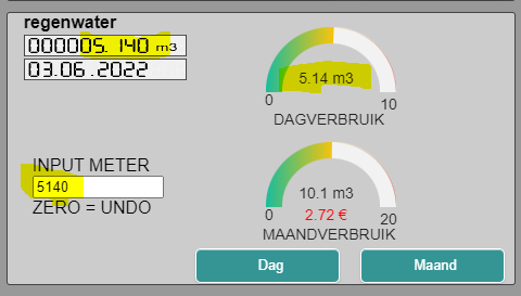
Creating a meter with manual entry of counter readings can be done by selecting 'Input man' under 'channel type' and giving a name to the output. Then press "SAVE" and... Read moreCreating a meter with manual entry of counter readings can be done by selecting ‘Input man’ under ‘channel type’ and giving a name to the output. Then press “SAVE” and confirm with the password “adminLOWI”
Once the log channel is created, you can enter the counter reading of your meter in liters (or in Watts) under DETAILS. IMPORTANT in liters/Watts because LoWi does not allow commas.
For example, enter 5,140 m³ as a number WITHOUT decimal point so 5140, immediately a date is addedYou can now enter these values daily, weekly or irregularly. LoWi creates differential meter readings and pastes the consumption on the correct date in your graph. You can enter multiple times per day but only the last value for that day is remembered.
-
6. How to upgrade LoWi via setup or manually?
In the LoWi setup page, you can read the version of your LoWi module. The version is a reverse date, e.g. 22.05.15.3 means that this firmware is the 3rd version... Read moreIn the LoWi setup page, you can read the version of your LoWi module. The version is a reverse date, e.g. 22.05.15.3 means that this firmware is the 3rd version from May 15, 2022.
- Most current version of LoWi3 :v23.9.2.1
- Most current version of LoWi :v23.9.3.1
Important in any upgrade is :
- There MUST be good and stable WiFi reception, WiFi signal strength can be read at RSSI. In the example it is -75dBm which is OK , from -80dBM and above WiFi is too weak for upgrade and for proper operation of the LoWi.
- There MUST be connection to the Internet, only if the NTP box turns green is there internet.
Once both are OK you can start upgrading LoWi and you can do that in 2 ways. Both methods give the same result.
Upgrade via the setup page:
Select “START” and confirm with password‘adminLOWI‘ . LoWi now starts a process of downloading, installing and rebooting and displays this through a timeline. During this process which can take up to 1-2 minutes do not disconnect LoWi. Give LoWi time to upgrade. After the upgrade, “READY” appears at the STOP/START button and the current version is displayed.
Manual upgrade via the switch on the LOWI stick:
If your LoWi is connected to WiFi as well as the Internet, you can determine this because the LED lights up briefly every 5 seconds (heartbeat LED) and then you can start upgrading. Activating the upgrade is done by pressing the switch for about 5 seconds until the LED is constantly lit, then releasing it. LoWi now starts a process of downloading, installing and rebooting and during this process which can take up to 1-2 minutes you should NOT disconnect the LoWi. Give LoWi time to upgrade. Once you have another heartbeat the upgrade is done. We show it again in the video below:
While rebooting, the LED goes on a first rapid flicker ( connection to the Internet and then a second rapid flicker ( connection to an NTP clock server) and then switches to heartbeat.
BETA version:
If the BETA checkbox is on in the LoWi3 or ReMI setup page it will automatically upgrade when a new firmware comes online. See at FAQ section A “How to make LoWi/ReMI upgrade automatically”
-
7. How can you give LoWi or ReMI a RESET (clear logs and config)?
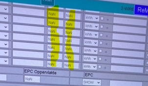
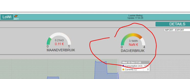
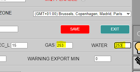
[one_half] If you want to completely clear ALL logs and the configuration of your LoWi or ReMI while retaining the current WIFI and IP settings, you can do so by... Read moreIf you want to completely clear ALL logs and the configuration of your LoWi or ReMI while retaining the current WIFI and IP settings, you can do so by entering the number 253 under gas and under water price (optionally the Using TAB key to jump to water), then press “SAVE” and confirm with password ‘adminREMI’ for ReMI or ‘adminLOWI’ for LoWi. Once SAVE is pressed, the ReMI/LoWi will start clearing its memory and then after about 20-60 seconds it will restart and be available within the same WiFi network and using the former IP address. During this process you may use the LoWi or ReMI DO NOT INTERRUPT!NaN values/ database corrupt: Reset is also needed if you see the value NaN in some fields on the LoWi or ReMI web page. NaN means that your database is corrupt and contains incorrect values. This may be because you have entered commas or special characters in the number fields, or because LoWi/ReMI is not given time to load its web page before pressing the SAVE button, or because of an unstable wifi connection e.g. during saving a configuration, …
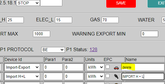
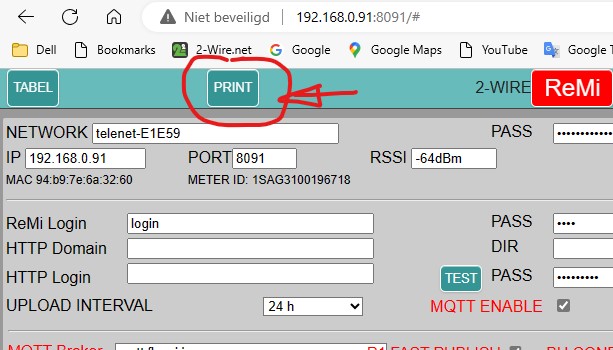
IMPORTANT Backup: With the PRINT button at the SETUP page you can make a pdf of your configuration, or if you have an MQTT token you can call up a copy of your configuration (see manual) Your history is not automatically saved, but you can make a link to EnergieID.be to save your data in the EnergieID cloud. Or you can link a second LoWi/ReMI/MEMo3 via MQTT to the first one as a backup.Clear one log channel: Should any exit logs show up during this process, you can delete them channel by channel by typing the word“delete” by the name of the channel you want to delete. Then press “SAVE” and confirm with password ‘adminREMI’ or ‘adminLOWI’ . You must not interrupt this process either. Afterwards, the former name automatically appears and the logs of that channel are cleared.
-
8. WiFi configuration via DHCP
The"DHCP to fix IP address" works for both LoWi3, ReMI and MEMo3 and you can do the setting from any smartphone, tablet or PC. Below we show how to set... Read moreThe“DHCP to fix IP address” works for both LoWi3, ReMI and MEMo3 and you can do the setting from any smartphone, tablet or PC.
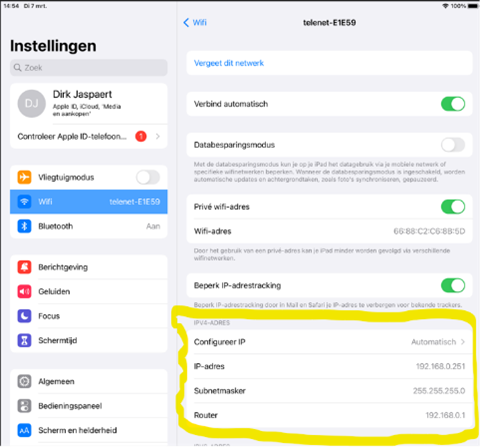
Below we show how to set up a LoWi3 via an Ipad/IPhone.1. Network settings of your ipad/iphone can be read through settings/WiFi and then click the “i” by your current network. Here you can then read the ipad IP address:
- IP address Ipad: 192.168.0.251
- SUBNET mask: 255.255.255.0
- Router:192.168.0.1
With this information, you could then determine a fixed IP address for LoWi/ReMI yourself, or you could also have the modem automatically populate a fix IP address for LoWi3 via DHCP.
We show the DHCP method here:2. Connect LoWi3 to the P1 adapter USB (to work easily during configuration), or connect to the P1 port of the digital meter.
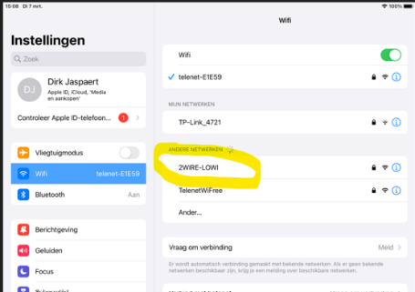
Once the LED flashes then press the switch for approx. 5..7 seconds until the LED is on continuously so that LoWi3/ReMI becomes a WiFi access point “2WIRE-LOWI” or “2WIRE-REMI”.NOTE If the LoWi3/ReMI was already connected to this wifi network and you still want to change the settings then press the switch for 5 seconds within 3 seconds of connecting.
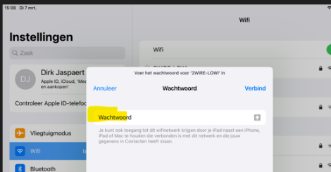
3. Double-click access point “2WIRE-LOWI” to let the ipad connect to LoWi/ReMI and enter “adminLOWI” (or “adminREMI”) as password. After about 10…30 seconds, the REDIRECT page automatically opens.
4. Once at the Redirect page click on “Configure WiFi.”
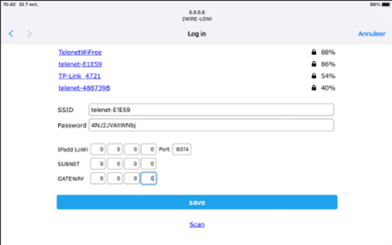
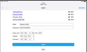
5. On the configuration page, select the WiFi network you want to connect to, provide the WiFi password and then enter four zeros(0.0.0.0) at:
- IPadd LoWi
- SUBNET
- GATEWAY
and a number between 8000 and 9000 by port number, e.g. the number 8500
Then press SAVE.
You will see another confirmation briefly and your LoWi/ReMI will now reboot itself and get a fix IP address from the WiFi modem.
Problem now is that you do not know this assigned IP address but there are now 3 methods to find out this IP address viz:
Through an IP server scanner, or through 2-WIRE’s windows IP server scanner, or through the REDIRECT page.6. Obtain IP address via the REDIRECT page: Repeat steps 2,3,4. Then click “Configure WiFi” and simply note the assigned IP address and port number of LoWi/ReMI.
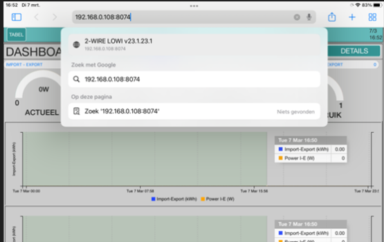
Afterwards, without pressing SAVE, disconnect the LoWi/ReMI and reboot. Or still press SAVE after which the LoWi3 boots up on its own.7. Connect the iPad to the local Wi-Fi network. Open the web browser and enter the noted “IP address : port number” in the toolbar to get to the LoWi page. Eg. 192.168.0.112:8112
This “fixed IP address via DHCP” method is platform-independent and works on any smartphone, tablet, PC or MAC as long as it has a Web browser. The online manual and the online Tutorials for LoWi and for ReMI explain this in even more detail.
-
9. Can LoWi3/ReMI be used to read voltage, current and power per phase?
Using the Flemish digital meter, it is possible to create several channels to measure total consumption across three phases, including total current and total power. In addition, a second channel... Read moreUsing the Flemish digital meter, it is possible to create several channels to measure total consumption across three phases, including total current and total power. In addition, a second channel can be set up to measure the total consumption across three phases along with the voltage, current and power of phase 1. Similarly, successive channels can be created for stage 2, stage 3, and so on.
In addition, the digital meter now offers the ability to read the current quarter power, updating power values every 5 to 10 seconds. Logs are also kept of the readings, recorded every 5 minutes for the last 10 days. A configuration example is shown below:
Channel CH02: Total consumption over 3 phases with total current and total power
Channel CH13: Total consumption over 3 phases + voltage, current and power of phase 1
Channel CH14: Total consumption over 3 phases + voltage, current and power of phase 2
…Quarter power readout: Updated every 5-10 seconds
Log frequency: Every 5 minutes
Maximum log history: Last 10 daysWith the configuration below, the Flemish digital meter provides extensive capabilities to monitor and analyze energy consumption and power in detail.
B. ReMI
-
1. How to make ReMI switch to the dynamic energy tariff?
Recently, there is the ability to smartly switch each of the 4 outputs of the ReMI and/or the paired 2-WIRE WiFi plugs based on the dynamic rate. This requires an... Read moreRecently, there is the ability to smartly switch each of the 4 outputs of the ReMI and/or the paired 2-WIRE WiFi plugs based on the dynamic rate. This requires an MQTT token annual subscription which you can order online at this website. Once MQTT is active, ReMI requests daily official “day-ahead” prices in Euro/MWh.
You can enter the MQTT token in the configuration page of the ReMI Web server. Check ‘MQTT enable’ 1, 2. Enter URL and Token (EXACTLY 64 characters long, be careful not to copy an extra space with it), 3. Save with password “adminREMI” and Saturn icon appears if MQTT is OK, 4. Check the firmware version (reverse date =24.6.14.1) and upgrade if necessary, 5.> Select your country code (NL Netherlands, BE Belgium, FR France, DK Denmark)
url: mqtt.flespi.io
token: exact64_characters_without-space_copy_otherwise_you_will_not_get_saturn_iconOnce the Saturn icon (3) appears there is linkage to the MQTT broker and loading of the day-ahead prices can begin.
The “day-ahead” prices only then become visible once you create logic with dynamic rates. (TIME shows the hours from 0 to 23 of a day, DYNAMIC PRICES are the current prices in Euro/MWh, DYNAMIC SORT the hours from cheapest to more expensive)So, in LOGICA at “Channel” select any energy channel, and then at ” Type” you can select one of the 3 dynamic logics:
3 functions are provided:
– Dynamic: Lower or higher than the set hourly price , (e.g. compare value=138 )
– Dynamic av: Lower or higher than the calculated current average daily price( here compare value=72) +/- percent(= diff, e.g. 72 +/-5%)
– Dynamic sort: Active only during the cheapest hours, number of hours adjustable (=compare value, e.g. 7 cheapest hours= 15,14,2,4,3,13,16 )At Output Channel you can then select one of the four outputs (17, 18, 19, 20), or an energy channel which is set as a smartplug (CH1..CH16).
-
2. Who can install ReMI for me?
Each recently purchased heat pump or heat pump boiler is equipped with 1 or 2 smart-grid ready contacts. For example, by connecting one or two conventional on/off light switches to... Read moreEach recently purchased heat pump or heat pump boiler is equipped with 1 or 2 smart-grid ready contacts. For example, by connecting one or two conventional on/off light switches to these smart-grid ready contacts, you could thus manually call a pre-programmed setting such as low, eco, normal or boost without disturbing the internal operation of the heat pump or heat pump boiler.
You could now replace this manual switch with a clock-time switch. This would allow you, for example, to heat your water heater overnight at the economy rate. But even better is to connect a ReMI module’s two relay switches to these smart-grid ready contacts. On the configuration page of the ReMI module, you can then set up your own logic to automatically switch these contacts based on the clock, injection, quarter power, or a combination of these parameters. In short, you can optimize the switching according to your preferences and monitor its effects “live” in the consumption graphs. Part of the purpose of this smart switch is to utilize excess solar energy in heating.
We often get the question of who can install this for the user. In our opinion, the most appropriate person for this is the person who performs maintenance on your heat pump or heat pump boiler. This person knows how to set the modes low, eco, normal, boost in the WP, WPB and knows the proper terminals of the smart-grid ready contacts. With the linked ReMI module, he, too, gets quick insight into the proper operation of the heat pump.
Indeed, not every installer is familiar with the ReMI module or knows how to connect ReMI to wifi and optimally configure it. Therefore, we have made some video tutorials available online. Even for someone with limited knowledge of PCs or smartphones, configuration is easy and can be done from any smartphone, tablet, PC or Mac. It is certainly not complicated, and on the second installation, the process will be considerably smoother.
-
3. How to upgrade ReMI manually or through setup?
In the ReMI setup page, you can read the version of your ReMI module. The version is a reverse date, e.g. 22.05.15.3 means that this firmware is the 3rd version... Read moreIn the ReMI setup page, you can read the version of your ReMI module. The version is a reverse date, e.g. 22.05.15.3 means that this firmware is the 3rd version from May 15, 2022.
Current version: v23.9.2.1
Important in any upgrade is :
- There MUST be good and stable WiFi reception, WiFi signal strength can be read at RSSI. In the example it is -75dBm and that is just OK , from -80dBM and above WiFi is too weak for upgrade and for proper operation of the ReMI.
- There MUST be connection to the Internet, only if the NTP box turns green is there internet.
Once this OK you can start upgrading ReMI and there are 2 ways to do that. Both methods give the same result.
Upgrade via the setup page:
Select “START” and confirm with password‘adminREMI‘ . ReMI now starts a process of downloading, installing and rebooting and displays this through a timeline.
Give ReMI time to upgrade: During this process which may take up to 1-2 minutes you should not disconnect the ReMI. After the upgrade, “READY” appears at the STOP/START button and the current version is displayed.Manual upgrade via the switch on the ReMI module:
If your ReMI is connected to WiFi as well as the Internet, you can determine this by the LED lighting up briefly every 5 seconds (heartbeat LED) and then you can start upgrading. Activating the upgrade is done by pressing the switch for about 5 seconds until the LED is constantly lit, then releasing it. ReMI now starts a process of downloading, installing and rebooting and during this process which may take up to 1-2 minutes you should NOT disconnect the ReMI. Give ReMI time to upgrade. Once you have another heartbeat the upgrade is done. We show it again in the video below:
BETA version:
If the BETA checkbox is on in the LoWi3 or ReMI setup page it will automatically upgrade when a new firmware comes online. See at FAQ section A “How to make LoWi/ReMI upgrade automatically.”
Returning to the manual upgrade version can then be done by checking BETA OFF and upgrading again. After RELOAD page, the blue check mark then disappeared.
-
4. Can I use ReMI to apply load balancing to my charging station?
A charging station with"load balancing" mode measures actual total consumption (and injection) of the home/building via the P1 port or an additional energy meter and then continuously adjusts the charging... Read moreA charging station with“load balancing” mode measures actual total consumption (and injection) of the home/building via the P1 port or an additional energy meter and then continuously adjusts the charging current based on this measured consumption. This ensures rapid charging of the car(s) and prevents the main fuse from tripping due to overloading.
In“SOLAR” mode, this EV controller looks at the measured injection and will try to charge the car with solar energy. And if there are multiple charging stations, the available charging current is distributed logically among the different charging stations according to the EV control setting.We briefly considered linking some sort of home automation functionality to ReMI, where ReMI could activate or take over this preset (LOADBALANCING/SOLAR/…) based on measured consumption, energy rates, etc. in the home. However, we think it is better to run this product specific setting through the EV APP, or EV display and the associated charging station control.
ReMI and ‘load balancing’ charging station
To still use ReMI in combination with a charging station, we let the ‘smart’ charging station switch itself based on measured consumption or measured injection, while we let the 4 ReMI relay outputs switch via configurable ReMI logic NOT on total consumption or injection but for example on the power of the inverter, on the consumption of the charging station, on weekly clocks, on quarter-hourly peaks, on energy tariffs, etc… In this way, both controls cannot start to work against each other and you can give priority in the ReMI logic to EV or to the house, and still separate from the EV control.Independent of the charging station controller, ReMI contacts are thus used to link to the smart energy input of a heat pump, boiler or storage heater, for example. And by playing with “delay ON” and “delay OFF,” we can then set priorities for charging the car or heating the home, which increases the self-consumption of solar power and avoids peak power.
For example: The water heater may only charge during night( clock or rate) or on injection, AND NOT when the EV is charging (put consumption meter on the charging station).
ReMI and ‘basic’ charging station
If you did choose a basic charging station without load balancing functionality, but with, for example, a “2-position” (low/boost) and an associated input contact, you could switch it with a contact from ReMI. For example, you can then activate the ‘BOOST’ mode when there is a lot of sun, the ‘LOW’ mode when there is peak consumption, and possibly combine this with energy tariffs and/or a schedule. In this way, control of the charging station is done through its “smartgrid ” input, a bit like heating control. -
5. Battery steering possible?
Question: I have an 11kW installation with 3-stage hybrid inverter and an 11kW battery. I'm interested in ReMi to control the management of appliances and boiler, but I don't see... Read moreQuestion: I have an 11kW installation with 3-stage hybrid inverter and an 11kW battery.
I’m interested in ReMi to control the management of appliances and boiler, but I don’t see info anywhere about measuring and controlling battery charge in your system. Am I overlooking something or is the battery not part of ReMi’s logic?Possible answer?
ReMI indeed cannot directly intervene in the control of some appliances simply because they do not allow it and because they do not have a smartgrid ready input like e.g. heat pumps. So it has to be another way.
Do you mean that a battery (controller) starts charging as soon as there is injection? So with a lot of sun the battery is charged at 10…12 hr, and at that time ReMI can take over.
So one would give the ReMI relays a “delay ON” of say 10 minutes. So when the battery is charged by noon, injection becomes available again and 10 minutes later, the relay/plug on the REMI will turn on and the paired device will be sent on injection. -
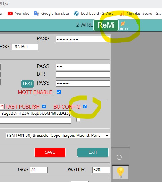
6. MQTT Backup of the LoWi3/ReMI configuration.
If MQTT is enabled in LoWi3 or ReMI then one can store a backup of the configuration in the cloud. Backup: check "BU CONFIG" and then save and confirm with... Read more -
7. ReMI logic facts
[full_width] [/full_width] The online manual accompanying the ReMI product sheet describes the operation of the ReMI logic in detail. In this FAQ, we want to briefly recap a few "facts".... Read moreThe online manual accompanying the ReMI product sheet describes the operation of the ReMI logic in detail. In this FAQ, we want to briefly recap a few “facts”.
- – ReMi has 16 log channels( or inputs) CH1 to CH16, and these can be log channels coming from the P1, via Modbus meters, MQTT values from another logger, MQTT plugs, pulse inputs, … . In addition to these 16 inputs, there are then 4 relay/solid-state outputs R17, R18, R19, R20
- – ReMI also has 4 more adjustable weekly clocks which can be incorporated into the logic.
- – Via simple if-then-else logic based on measured values from the 16 inputs, one can intelligently switch the 4 relay outputs and/or the PLUGGEN inputs (MQTT Plug).
- – the various Columns:
- + At CHANNEL one selects a log channel
- + At TYPE select a measured parameter of that log channel (power, Tp temperature, voltage,…)
- + With COMPARE VALUE, the measured parameter is compared to a set COMPARE VALUE every minute. The DIFF is the differential or e.g. the power of the device to be switched. In the above example (line 1), the logic becomes TRUE at 1501 watts injection, and TRUE as soon as the measured value drops below VALUE -DIFF value = 99 watts.
CAUTION: DO NOT use negative numbers or NO negative result for VALUE -DIFF!!! - + Delay On: Only if the condition remains TRUE during this time will the outputs switch
- + Delay Off: If the condition remains ON during this time the outputs will switch
- + Output Channel: Here one chooses output R17, R18, SS 19, SS20 on the ReMI module or a log channel 1..16 which is set as MQTT plug.
In our example, there is one logic which sets R17 ON and there is a second logic line to set R17 OFF.
With FOLLOW, plug 11 becomes ON if logic is TRUE for 3 minutes and plug 11 becomes OFF if injection is less than 300 watts for 1 minute
- – In the column ‘Logic Overrule can be set with the output or plug manually ON, or manually OFF, or to LOGICA where the color of the logic button:
-
- + Red= ON= TRUE
- + Green= OFF= TRUE
-
NOTE: So the color of the logic button does NOT determine physical state of the relay. You can see the relay status on the module’s LED R1 and R2.
Logic is executed line by line every minute , i.e. the last line will determine the status of the output.
A relay can be driven TRUE and FALSE at the same time but then the last line determines the state of the paired relay.
It’s always best to test your logic by playing around with the readings a bit.
C. MEMo3
-
1. Why are logs sometimes missing from the MEMo graphs?
MEMo communicates continuously and without interruption over multiple channels and with multiple protocols: LAN, WiFi, NTP, Modbus, LoRa, smtp, http, MQTT, SPI, rs232, SD, P1, ... If there is interference... Read moreMEMo communicates continuously and without interruption over multiple channels and with multiple protocols: LAN, WiFi, NTP, Modbus, LoRa, smtp, http, MQTT, SPI, rs232, SD, P1, … If there is interference on one of those communication methods, or if e.g.
no response from the addressed device because it is configured but not connected or the device is defective, or there has been a power failure or network failure, and/or … then MEMo still keeps trying to communicate again.
If the failure persists, then there is a risk that MEMo will then loop on that and an automatic software self-reset will follow, and if that doesn’t help, a hardware reset will follow after several attempts.
But sometimes human intervention is still needed and one has to reboot MEMO by interrupting the power or by pressing the reset button briefly.
Annoying indeed, but 100% autonomous devices ( grass robots, PC’ s, self-driving cars, …) do not exist (yet).
So regular monitoring is important.
It is also important to try to eliminate failures.
Finding the failure can be done e.g. by setting up a mail server so you get messages from MEMo when something goes wrong.
See FAQ C3 https://www.2-wire.net/veel-gestelde-vragen/#memo3 Or as one does in important installations, placing a second device which will monitor the first.
For example, have MEMo monitored by a MEGA which will ask MEMO for meter readings and consumption every hour, and which will send an e-mail notification if a connected meter or the web server itself does not communicate, after which you can intervene. -
2. SUBTOTALS: calculate and generate
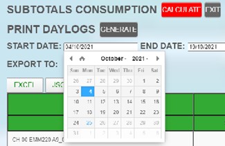
In the menu on the left, click on "SUBTOTALS. The image below now appears. [two_third] There are 2 features on this web page: The 'CALCULATE ' button is used to... Read moreIn the menu on the left, click on “SUBTOTALS. The image below now appears.
There are 2 features on this web page:
- The ‘CALCULATE ‘ button is used to display counter readings between a START DATE and END DATE and that along with the logged consumption.
- The ‘GENERATE‘ button calculates a 5’ detail of the START DATE and exports it to Excel.
CALCULATE
Click on the field next to “START DATE” and you will now see a calendar. Select the start date for the desired period. Do the same for the end date ‘END DATE’. (By default, it is set to the current time). Note that ‘END DATE‘ must be a date yesterday or older.
NOTES. The period of 1 day in SUBTOTALS is too small, especially if the starting day is the day of configuration.
Afterwards, click the “CALCULATE” button.
- The screen will now show all intermediate totals of the log channels.
(log channels of CO2 or temperature are not included in this table, only ‘consumers’) - The waiting time for calculation may vary according to the period and number of channels.(e.g. Period 9 months, with 20 channels may take about 8 sec), please do not interrupt the process.
- The table shows first the meter name, then the meter reading of the start time (STARTVALUE), and then meter reading of the end time (ENDVALUE).
Meter readings, also read on the display of each meter, and also read every minute under the corresponding CH number in MEMo3, are recorded every minute via Modbus and stored as values on the internal SD card for up to 3 years.
SUBTOTALS always shows the meter reading at 00.00 hr start day and this one at 23.45 hr end day. You can then export these meter readings to Excel to take the difference of these two meter readings yourself and that is the exact consumption over the set period which one can use for billing of energy costs.
- DIFF and COST: every hour a difference meter reading (= hourly consumption ) and a cost per hour are calculated in MEMo3 according to the values entered at the ‘SETTINGS’ and that intended for display in the daily and monthly graphs.
In the DIFF and COST columns at SUBTOTALS, you see the sum of all these hourly consumptions and hourly charges over the set period AND these are not necessarily equal to the difference of the displayed meter readings:- If the data logger has missed an hourly consumption, or the web server has been down for a while, or for a particular day the end counter is > start counter because e.g. the Modbus meter was replaced that day, or because the voltage on a pulse counter was interrupted so that it restarts at zero, or because you create a new meter on an existing Modbus address without clearing it first, then the start counter for that day is assumed to be zero when calculating the DIFF and COST for that day then the sum does not add up to the difference of meter readings, so these values are informative and thus better NOT to use for billing costs. For settlement, use the meter readings from above.
NOTES. A pulse counter on an RG.016, REL.44 module resets to zero when the voltage is interrupted.
SEARCH: In the ‘Search’ field you can type in part of a name and then only the consumers whose search word appears in their name will be shown. At the top of the table there are now some ‘buttons’: these allow us to export the displayed table with the filename = ‘SUBTOTALS ENERGY year_month-day-hour-minute’, and the extension:
-
- EXCEL: ‘.xlsx’
- JSON: ‘.json’
- CSV: ‘.csv’
- PRINT: ‘.pdf’
NOTES. The export choices ‘EXCEL’, ‘JSON’ are not supported on many tablets (certainly not IPAD), full support under Microsoft-windows.
Important: CARE FOR BACKUP All recorded data, including meter readings, are stored on an internal SD card. If something goes wrong with this SD card, one loses both the configuration of the system and also the logged meter readings.
In the setup page you can make a printout in Excel form of the configuration, please save it digitally. In SUBTOTALS, one would take an export/outprint of the meter readings at least once a month in case something goes wrong with the MEMo3.
MEMo3 is only a (low-cost) hardware module, there are no free or paid services associated with the MEMo3 module, there is also no backup guarantee for the stored data.GENERATE
EXPORT AMR DAY FILES LOCALLY TO EXCEL
This function generates an Excel file of a given date containing all readings and counter readings at 5-minute intervals.
select the day with ‘START DATE’. (END DATE has no function now)
Press “GENERATE.
After about 20-30 seconds, the csv file will be ready to open in your download folder (EXCEL).
This csv file then contains all the readings of that day with an interval of 5′ -
3. Remote access via the APP_HTML
To access a MEMo3 Web server from outside the local network, one can use the APP_HTML in addition to portforwarding. The html file (APP_MEMO3B.html) can be downloaded as a ZIP... Read moreTo access a MEMo3 Web server from outside the local network, one can use the APP_HTML in addition to portforwarding.
The html file (APP_MEMO3B.html) can be downloaded as a ZIP file from the MEMo3 product page and saved on your PC’s local drive. When you click this file, it opens in the web browser. You can enter up to 4 MEMo3 Web servers in this application to access them remotely for readout or configuration. In the tutorials below, we show the different steps:
- – Go to MEMo3 web server home page and set Level3 (installer level) there
- – Go to ‘CONFIGURATION/SETTINGS’ to the MQTT section and enter:
- – MQTT Broker: mqtt.flespi.io
- – MQTT Token: my_token_with_exact_64 characters_and_let_erop_to_not_space_with_copy
- – MQTT Password: APP_HTML
- – Press the TEST MQTT button and when it turns green after a few seconds, the pairing with MQTT has been made. All created log channels are now automatically published to the MQTT broker every minute. Also, one can now “subscribe” to log channels from other 2-WIRE Web servers (LoWi3,ReMI, MEMo3) or 2-WIRE MQTT plugs THEo, …
- – Go to the Homegina where each created channel should be re-saved to load it a first time to MQTT. Also, you should move at least one channel for a moment with the ‘SORT CHANNELS’ button and then confirm with ‘SAVE LAYOUT’ button.
- – Now from Windows explorer, click the file APP_MEMO3B.html so that it opens in the web browser. In the MAC field, select one of the 4 blank lines and press edit. Then enter a NAME/ MAC address and in the second field the MQTT token followed by ENTER and from now on you can access the selected web server.
- – If you want to change an already entered line, select that line , click EDIT and replace the token with the word “delete” followed by ENTER and this line will be deleted after which you can enter another Web server.
-
4. Email notification with MEMo3
If you wish to check the operation of the WS.503 on a daily basis, you must activate the mail server. But also with 'logic', 'alerts' can be set which send... Read moreIf you wish to check the operation of the WS.503 on a daily basis, you must activate the mail server.
But also with ‘logic’, ‘alerts’ can be set which send an email when limits for consumption or temperatures are exceeded. If you have an email account with a provider, you can enter the address of the outgoing mail server (e.g. uit.telenet.be), your own mail address (Sender Address) and a password (Pass). You can send the alerts to up to 2 email addresses. (Mail Address1 and Mail Address 2)
After sending settings, a test mail is sent to the specified mail address1
(may take up to 5sec to confirm settings. – red is error in settings, green = OK).With some providers, this mail ends up in SPAM. At telenet no problem.
For example, the configuration in MEMo3 looks like this:
With a proximus modem that will be:
- Mail server: relay.proximus.be
- Sender address: xxxxxx@proximus.be and Pass: my-password-of-my-proximus-email
- Receiver Mail address 1 yyyy@telenet.be and Mail address 2(Cc) zzzz@proximus.be
An example of a daily email notification with the error messages:
One can also use the logic to start sending out email notifications at conditions to be set by oneself (see manual chapter Logic).
-
5. Delete logs in MEMo3
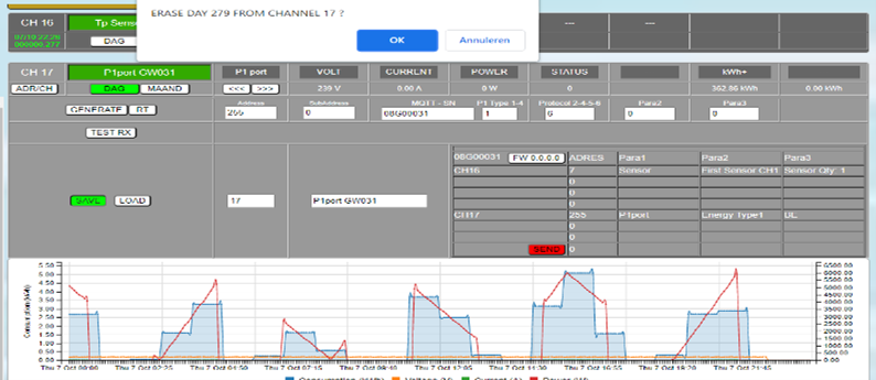
Sometimes we want to delete logs from 1 particular day or month when we have implemented a different meter or configuration on that channel. Clear Day Log: Open configuration of... Read moreSometimes we want to delete logs from 1 particular day or month when we have implemented a different meter or configuration on that channel.
Clear Day Log: Open configuration of that channel, and open the day graph.
You set the address to 255. You now get the message: ‘ERASE DAY xx ?…’. Click “OK.The address is automatically reset to its set address after deletion. After closing and opening graph, this day is cleared.
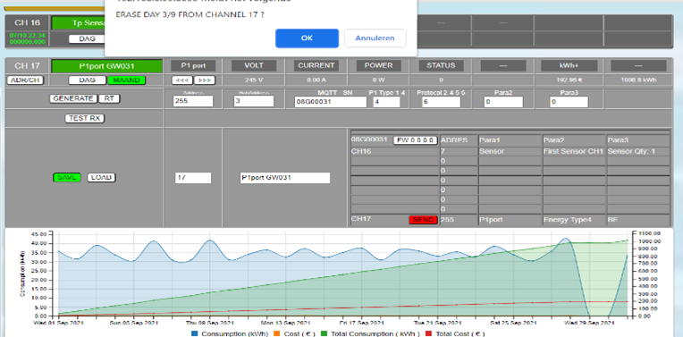
Want to do the same thing but also in the monthly chart?
Then open the monthly chart, choose the desired month, and set the address to 255.
The subaddress determines the desired day of the selected month. Click ‘OK’ for execution
Delete full month: The subaddress also set to 255 will clear the entire month. -
6. Upgrading MEMo3 via web server
You can upgrade MEMo3's firmware in 2 ways, viz. Upgrade via the display, this method is explained in the MEMo3 video tutorials. This method can be used if you do... Read moreYou can upgrade MEMo3’s firmware in 2 ways, viz.
- Upgrade via the display, this method is explained in the MEMo3 video tutorials. This method can be used if you do not have access to the web server, or if your css or javascript is damaged for some reason.
- Upgrade via web server. This method is preferred because here you have a better view of the process ( version, run time, …). You can see how the upgrade is done in the video below, the different steps:
Go to configuration/settings
Click the “Firmware versions” button to view the version available and the version installed. The version number is a reverse date v(YY-MM-DD-nr). The upgrade is done in 2 steps:
- STEP 1: Press the “DOWNLOAD” button to download the firmware of the various Modbus modules and temporarily save it to the internal SD card. Later via the Channels, one can then go about upgrading over Modbus module by module where this stored firmware is loaded to the respective Modbus module. If a GREEN CHECK is shown everywhere, this step was successful. If not successful then test IP settings and try again.
- STEP 2: Only after step 1 is successful may you press the “INSTALL” button to start upgrading the web server itself. When the upgrade is over, MEMO3 will reboot and the web page will reload.
Briefly summarized again in this tutorial:
x
-
7. How do you read the MEMo graphs on a 3 phase meter?
2-Wire has a number of different 3-phase meters ( EMM.630 series) either with direct current passage or current probes. These 3-F meters are primarily intended for 3P4 or 3x380V+N connection,... Read more2-Wire has a number of different 3-phase meters ( EMM.630 series) either with direct current passage or current probes. These 3-F meters are primarily intended for 3P4 or 3x380V+N connection, but can also be set , connected and used as a 3x230V (3P3)*meter or as a mono-phase meter (1P2).
*With 3P3 configuration, current and power of Phase 2 are not shown in the graphs.
- Readings: On the display of these meters, you can start reading a number of measurement variables such as voltage, current, power, frequency, power factor,… per phase or as a total over the three phases. Of those many parameters, MEMo records voltage, current, power in KW, reactive power in KVar, power factor and that for each of the 3 phases. These readings are stored for a maximum of 3 years on the MEMo3 internal SD with 1 minute resolution.
On the web server daily graphs are shown, per phase, with adjustable resolution voltage and current and power and thus we arrive at 3 graphs per 3-phase meter. (see bitmap below)
– Phase 1
(sub-address 0): voltage between neuter and phase, current, power
– Phase 2
(sub-address 1): voltage between neuter and phase, current, power
– Phase 3
(sub-address 2): voltage between neuter and phase, current, power
The current power of each phase is also shown at the top of the closed graph
- Meter readings: In addition to meter variables, there are incremental consumption counters which records the total consumption ( active and reactive) over the 3 phases. MEMo records every minute the active consumption meter readings IMPORT and EXPORT(=injection) expressed in kWh. These meter readings remain stored on SD for up to 3 years. You can read these 2 meter readings on the meter display or in the web server (light green numbers) after pressing auto-refresh.
In the webserver graphs we do not show these meter readings, but we do show the one-hour difference between two consecutive meter readings each time and that for the 2 power directions, i.e. the consumption (IMPORT) over one hour in kWh, and the injection (EXPORT) over one hour in kWh.- IMPORT hourly consumption across the 3 phases is then appended to the graph of Phase 1
- EXPORT hourly consumption across the 3 phases is then appended to the graph of Phase 2
- So with Phase 3, you don’t see a consumption graph
The daily consumption (= counter position 00.00Hr – counter position 24.00H) and annual consumption (=Counter position January 1 – counter position today) is shown as a value at the top of the closed graph
The monthly graphs show daily consumption along with energy costs.Remark:
- – MEMO reads the same Modbus registers each time, so when the power meter is in 3P3 mode, the power and current of phase 2 is displayed as zero. This does not mean the meter is measuring wrong just that the registers are reading current and power incorrectly.
- – If the meter is reverse connected then the power is negative and this is displayed as power=zero in the web server.
- – With calorimeters, the measured values are : departure and return temperature, flow rate, power and in addition the 2 counter readings with consumption heating and consumption cooling. Optionally, 2 sanitary water meters can be linked whose flow and water consumption are then logged and displayed in the graphs.
- – Idem with a mono-phase meter ( type EMM.120 or EMM.220) under subaddress ‘0’ comes the IMPORT graph and under subaddress ‘1’ , at the 2nd phase so to speak, the EXPORT graph. Voltage , current, and power is then under subaddress’0′.
Figure. In the figure below, only daily chart Phase 1 is unfolded. The curves show voltage, current, power of phase 1 , the blue graph shows the hourly consumption across the 3 phases together, calculated as the one-hour difference between two consecutive meter readings each time expressed in kWh.
- – The graph header of phase 1 shows : actual power phase 1, day-consumption IMPORT over the 3 phases from midnight to now, annual consumption IMPORT over the 3 phases from New Year to now.
- – The graph header of phase 2 shows : actual power phase 2, daily consumption EXPORT over the 3 phases from midnight to now, annual consumption EXPORT over the 3 phases from New Year to now.
- – The graph header of stage 3 shows only current power stage 3.
- Readings: On the display of these meters, you can start reading a number of measurement variables such as voltage, current, power, frequency, power factor,… per phase or as a total over the three phases. Of those many parameters, MEMo records voltage, current, power in KW, reactive power in KVar, power factor and that for each of the 3 phases. These readings are stored for a maximum of 3 years on the MEMo3 internal SD with 1 minute resolution.
D. Modbus Energiemeter
-
1. How accurately can you measure with a current coil?
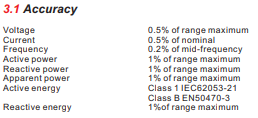
EMM energy meters are all calibrated meters with high measurement accuracy. The meters with extra MID indication are calibrated under the supervision of a recognized inspection body (SGS) and are... Read moreEMM energy meters are all calibrated meters with high measurement accuracy. The meters with extra MID indication are calibrated under the supervision of a recognized inspection body (SGS) and are suitable for energy cost billing.
The measurement error versus the different measured variables and consumptions can be found in the online product sheets.
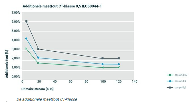
In meters with current clamps, in addition to the measurement error of the meter, you also have the measurement error of the coupled coil, both measurement errors one must add up. The measurement coils in our price list are class 0.5 (or class 1) and have a measurement error of +-0.5% (or +-1% for class1) when used in 20 to 120 percent of the coil’s nominal measurement range.
In other words, if the current to be measured is less than 20% of the nominal current of the coil, it means that the deviation is greater than this 1%. Especially in the range <5% of the rated current, the percentage measurement error can be very sharp, as you can see in the graph below, hence the reason why it is important to choose the measurement coil according to the current to be measured. The cos phi of your installation also has a great influence on the measurement. -
2. Connecting and setting up EMM.630 CT MID
Surely there are some concerns when connecting a 3 phase meter with power coils. Choosing the right coil: EMM.630 CT MID is adjustable with 1A or 5A as the secondary... Read moreSurely there are some concerns when connecting a 3 phase meter with power coils.
Choosing the right coil:
EMM.630 CT MID is adjustable with 1A or 5A as the secondary current, the primary current is chosen according to the measuring current. To measure accurately, the measurement steam is between 20% and 120% of the CT value. Sample measuring current approx . 35A , choose coil 100A/1A or 100/5A coil.
At measuring currents << 20% the error rises quickly( See FAQ D2), choose smaller coils or for small powers where very accurate measurements are required, consider working without coils(EMM.630 MID). Indeed, the shunt measurement principle (direct current flow) works very accurately even at smaller currents.Connecting:
- Avoid voltage surge: connect coil conductors to meter first, only then clip coil around current-carrying conductor!!! Power coil installation by skilled electrical installer only!!! Wear safety glasses for every handling of the coils!!!
- Power supply meter: The meter is supplied 230Volt fused to terminal 5(Neuter) and terminal 6(Phase)
- Current coil and reference voltage: The meter serves both 380V+N and 3x23O adjustable via the display. For 3x230V, only 2 CT are needed because I2 is calculated I1+I2+I3=0. One consequence is that with a 3P3 grid current and power is not logged in MEMo3.
- Important to follow exactly the connection diagram, the measured reference voltage and the measured current MUST be on the same phase: ALWAYS test with voltmeter: Voltage between conductor reference voltage L1 and conductor current coil L1 must be ZERO, otherwise the measurement is wrong.
e.g.. At 3P4 connection: voltage L1 is measured at terminal 4, current L1 is measured at terminals 19 and 20 - Polarity: via display key “P” check polarity, if negative power (Watts) or negative PF then open and reverse coil, unless there would be injection by solar panels!
Configuration on the display:
To avoid fraud, the EMM.630 CT-MID the coil type can be entered only once, wrong entry= disposable meter:
- Secondary coil current: 1Ampere or 5Ampere: example with 5A:
SET Ct2 5
- Multiplier = ratio of primary/ to secondary current of the coil, Eg. 100A/5A=20 then here becomes:
Ct rATE 0020
In case Rogowski: CT1 should be set to 1kA
In the film below, we show the configuration for a 100A/1A coil. So here SET Ct2 1 and Ct rATE 0100
-
3. Counter readings on the display of the EMM.630 series
With the EMM.630 MID can measure some 40 values including 6 ascending counter readings: 1. Import (=consumption) active energy in kWh 2. Export (=injection) active energy in kWh 3. Imports... Read moreWith the EMM.630 MID can measure some 40 values including 6 ascending counter readings:
1. Import (=consumption) active energy in kWh
2. Export (=injection) active energy in kWh
3. Imports + exports or the total active energy through the meter in kWh
4. Imports of reactive energy in kVAh
5. Reactive energy exports in kVAh
6. Imports + exports or total reactive energy through the meter in kVAhCaution:
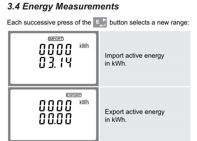
– read the following meter reading as follows: 0000 0314.14 kWh
So the 2 numbers stuck together!!!
– In our loggers, both kWh counter readings, import (=consumption) and export(=injection) are logged separately. One recognizes these meters by the indication import or export on the display.
A summation sign (M symbol turned on its side) represents import+export
– In fact, to know a (Belgian ferraris) reversing counter reading one must simply take the difference: import – export= reversing meter
E. Algemeen
-
1. Using Google Chrome to create a Windows app to the 2-WIRE Web server
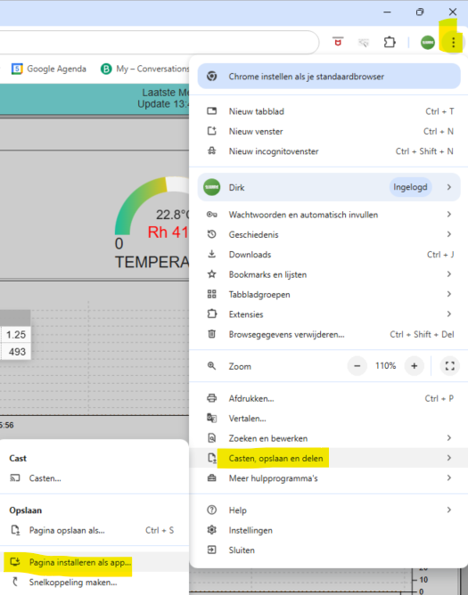
[two_third]Open google chrome Go to the home page of your 2-wire web server by entering the IP address + port number. Select the 3 dots, select "cast, save and... Read more -
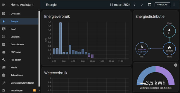
2. How to pass 2WIRE data to Home Assistant
We regularly receive requests to pass data (P1, Modbus meters, pulse counters, etc.) from the LoWi, ReMI and MEMo log channels to Home Assistant. So we worked out some sample... Read moreWe regularly receive requests to pass data (P1, Modbus meters, pulse counters, etc.) from the LoWi, ReMI and MEMo log channels to Home Assistant.
So we worked out some sample codes and collected them in a PDF document. This document is now available for download from the MQTT Token product page. Note that you do not necessarily need to use 2-Wire’s MQTT server for this integration.We hope these examples can get you started. But we do want to emphasize that we cannot offer support in developing a Home Assistant application.
-
3. Remote access as an administrator
Through portforwarding ( FAQ E), you will get to the login page of your 2-wire web server ( LoWi3, ReMI, MEMo3). From remote (different network), you can login with the... Read moreThrough portforwarding ( FAQ E), you will get to the login page of your 2-wire web server ( LoWi3, ReMI, MEMo3).
From remote (different network), you can login with the chosen login and password found on the setup web page of each web server.
However, this “visitor” cannot make changes unless:MEMo3:
If you still want to access the configuration via remote, you need to log in with the login, followed by the MAC address, and then the password.
Eg MAC = 12:fe:98:14:e5:b4 and the login is administrator, pass 4789,
Then you can log in with administrator12fe9814e5b4 and pass 4789
After end of session best log out ! (LOGOUT)
NOTES. As a “visitor” from outside the home network, you will NOT see the MAC address in the configuration!NOTES. An alternative to portforwarding at MEMo3 is the APP_HTML, this application provides remote access via MQTT, also applicable to a GPRS modem with SIM card
LoWi3 and ReMI
If you still want to access the configuration via remote, you need to log in with the login, followed by the MAC address, and then the MAC address.
Eg MAC = 12:fe:98:14:e5:b4 and the login is administrator, pass 4789,
Then you can log in with administrator12fe9814e5b4 and pass 12fe9814e5b4
After end of session best log out ! (LOGOUT)
NOTES. As a “visitor,” you do NOT see the MAC address in the configuration! -
4. Why the choice of Web servers instead of an app or cloud service?
There are several reasons why we at 2-wire chose to use a local Web server instead of an app or cloud application: Platform independence: Our web servers LoWi3, ReMI, MilO,... Read moreThere are several reasons why we at 2-wire chose to use a local Web server instead of an app or cloud application:
- Platform independence: Our web servers LoWi3, ReMI, MilO, MEMo3 use standard web technologies such as HTML, CSS and JavaScript, which are supported by various operating systems and devices. This allows users to access the Web application from different devices, such as computers, smartphones and tablets, regardless of the operating system or screen size they are using.
- No subscription cost: The storage, processing and visualization of the recorded data is all done locally in the LoWi, ReMI, MEMo3 module. That could potentially be important for privacy reasons but that also ensures that no processing and storage is needed on a central server as with an app or with a cloud application, and of course that also means no cost or dependency for such a server.
- Easy updates and maintenance: With a Web server, updates and changes can be performed centrally. Users do not have to download and install a new version of an app; instead, the Web application is updated on the Web server and users have instant access to the latest version when they open the Web page. This makes application management and maintenance easier and more efficient.
- No installation required: When using a Web server, there is no need to download and install an app on the user’s device. Users can simply open a Web browser and enter the URL of the Web application to access it directly. This makes it approachable for users to use the application without having to take extra steps to install it.
- Easy accessibility: A Web server offers worldwide accessibility, as long as there is an Internet connection. One needs to set up a “port-forwarding” in the Internet modem and from then on, users can access the Web application from any location and at any time, making it convenient for both local and remote users.
- Data sharing: Data is stored locally in the Web server and thus can also be easily shared between it and other Web servers, with external controllers, with a central management platform, with external apps,…
- Manufacturer independent: Because the web server is installed in the LoWi, ReMI, MEMo module itself, data reading, processing and visualization occurs completely locally. This makes one independent of 2-wire’s central data processing as a manufacturer; As long as the module is there, there is energy monitoring.
- Easy configuration: Configuration of the modules and connected meters is also done via web pages in the web server. Again, no PC software, app or license is required to add meters, switch logic or set up IoT accounts. This makes configuration very easy and can even be done remotely without the need for software on the customer’s computer or tablet.
- Control based on measured consumption: The local web server module records total and partial consumption, and via the web server one can set one’s own logic for smart control (ReMI, MEMo3) of the major consumers.
- Lower development costs: Compared to developing an app for different operating systems, building a Web server and an associated Web application is a lot more difficult but ultimately more cost-effective. Web technologies allow our developers to create a single codebase that can run on different devices and operating systems, reducing development time and cost.
Of course, there are situations where an app or cloud application may be more appropriate, depending on the specific requirements and intended use case. It all depends on the specific needs and goals of the project. For this reason, we still have two options for pumping data to a central application.
- Linking IoT:
The recorded data is stored locally in the in the LoWi/ReMI/ MEMo web server module, resolution and time of storage depends on the type of web server.
To still enable data exchange between Web servers, to an app or to a central application or server, we added both MQTT and HTTP functionality to each of these Web servers.
A few examples with external applications can be found on our Internet Of Things web page.
And for the MEMo3, we have developed a unique platform-independent html APP which you can download from the MEMo3 product page.
-
5. Auto-reboot LoWi/ReMI/MEMo3
The Web servers all have an " auto reboot" under certain conditions: LoWi3: every minute test wifi connect and if no connection for more than 5 minutes: soft reboot notice.... Read moreThe Web servers all have an ” auto reboot” under certain conditions:
LoWi3:
- every minute test wifi connect and if no connection for more than 5 minutes: soft reboot
- notice. With LoWi3 working, briefly press the switch to reboot
ReMi and MEMo3:
Hardware reboot is preceded by Soft reboot and only when soft reboot fails does HW take over.
Reason soft reboot:
- Slow wifi ( public network with high load)
- High load web server, e.g. with 3 pc on the same web server
- NTP server aborted due to too slow connection
- P1 configured but not connected
- MQTT broker responds poorly
- UDP every second for IP server scanning
- Too many processes configured simultaneously: http (5’+24hr) + MQTT+ fast publish+ 16 channels
Hardware reboot
- ReMI:
HW watchdog after 60sec if the program ‘loop’ was blocked by unknown reason (could also be buffer overflow)
Reboot if VCC < 3.1v (e.g. too little power supplied by P1 port)
Every minute test WiFi connection, but no HW reboot if no connection
Reboot if MQTT token entered incorrectly. - MEMo3:
If MQTT: test connection every minute. If no connection for more than 10 min: reboot
So if the token or url is entered incorrectly, the memo will reboot every 10 minutes !
Every minute test connection WiFi (if enabled). Reconnect with wifi if disconnect, but no reboot
HW watchdog after 60sec if the program ‘loop’ was blocked by unknown reason (could also be buffer overflow)
If RF used, test RF connection every minute, otherwise reinit RF driver (no reboot)
So Memo continues to log on without wifi or LAN.
Overall conclusion: The stability of the MQTT broker is very important for the proper operation of all modules.
Avoid configuration of non-existent meters otherwise the Web server will try to reconnect each time. -
6. PRINT configuration
LoWi3 and ReMI: PRINT config: For our support service, it is important to get a pdf of the current LoWi3 or ReMI configuration. To create such a pdf, go to... Read moreLoWi3 and ReMI:
- PRINT config: For our support service, it is important to get a pdf of the current LoWi3 or ReMI configuration. To create such a pdf, go to the setup page and press the PRINT button to generate a pdf.
- PRINT P1 status: In the setup page of LoWi3/ReMI, you can read the data string of the P1 port: In the setup page, press P1 Status , and the output of the P1 is displayed on your screen and copied directly to your clipboard. With CTRL V you can now paste this output into an email and deliver it to our support service.
MEMo3:
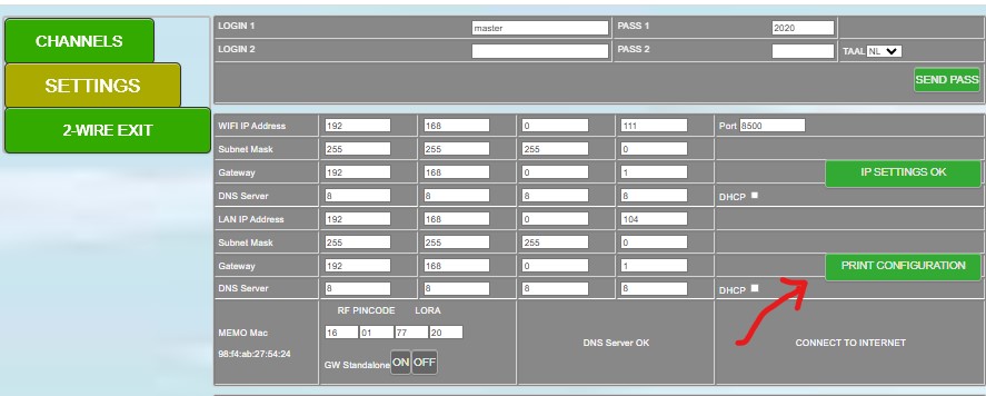
- At MEMo3, go to configuration/settings. Here you press the “PRINT CONFIGURATION” button after which an Excel file is created with all the configuration parameters. This printout is then best saved somewhere on the PC in case something goes wrong.
-
7. How can you set up port forwarding in your telenet modem?
LoWi, ReMI, MiLo, MEMo are Web servers with a local fixed IP address and their own port number, example '192.168.0.123:8081'. Any device within the local network can surf web pages... Read moreLoWi, ReMI, MiLo, MEMo are Web servers with a local fixed IP address and their own port number, example ‘192.168.0.123:8081’.
Any device within the local network can surf web pages on the web server through this IP address.Now to access the local Web servers from outside the home, you can start setting up port forwarding in the Internet modem.
The way to do this is different for every modem but the principle is basically the same everywhere, we show how to do it for a telenet modem:Note: the advantage to a telenet modem is that its IP address remains unchanged for a longer period of time ( several months). With modems with Internet via sim card, this IP address can change within a few hours already and there port forwarding makes little sense.
During the configuration of your web server, you set up a fixed IP address, a port number and also a login in password for access from outside and we’ll keep these handy for a while.
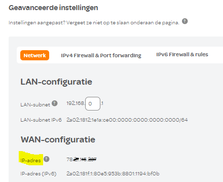
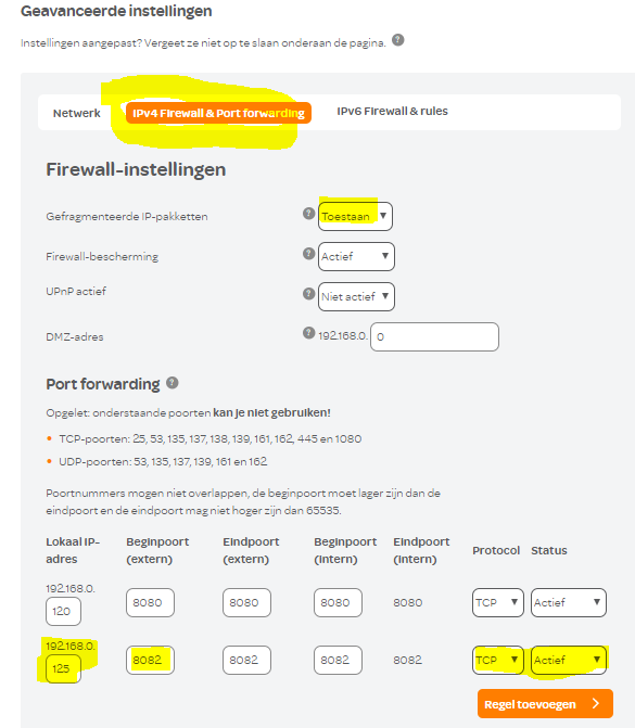
Surf to ‘my telenet’ and log in to your account. Go to your ‘home network’ , then ‘modem details’ and then ‘advanced settings’.
Under the ‘Network’ tab you can read the IP address of your modem, make a note of this IP address
In the next tab ‘IPv4 Firewall and Portforwarding’ enter your local ip address and port number. Also check your firewall settings right away. If you want to be able to upgrade your LoWi/MiLo/ReMI/MEMo then ‘Fragmented IP packets’ should also be set to ‘allow’ state. Then save everything and from now on you can surf from outside your home to your LoWi web server using the IP address of your modem followed by the port number of your web server. example: http://111.222.333.444.8082 , and of course login and password when surfing from outside.This login and password can be found in the setup page of LoWi3, ReMI, MiLo and MEMo3 and can only be changed when logged in locally.
For LoWi: ‘LOWI’ and ‘17.1.1.1 ‘ or ‘LOWI’ and ‘20.1.1.1 ‘
For ReMI: ‘REMI’ and ‘20.1.1.1 ‘
Note: changes to the configuration of LoWi , ReMi, MEMo3 or MiLo can only be made from the local network, not from outside unless you know the MAC address and log in as administrator (see manual or FAQ Remote access as administrator).
Portforwarding proximus modem:
How to set up portforwarding can be found on the proximus website: link proximus
But at the EDPnet, the explanation is a lot better: link EDP
Dynamic IP address :
Of course, you can also set up a dynamic IP address through DYN DNS.
Here you link the ip address of your modem to a host name which is easier to remember and which will track the change in your IP address.
Page not found...
The page you are looking for might have been removed, had its name changed or is temporarily unavailable.
Page not found...
The page you are looking for might have been removed, had its name changed or is temporarily unavailable.

