Energy monitor
on Web Server
Configurating the MEMo2 webserver
Configure the MEMo2 installation yourself from the web browser on your tablet or PC
On the web page below we will post short YouTube Tutorials to briefly explain the configuration and functionalities of the MEMo2 web server. The complete manual can be downloaded here: MEMo2 Handleiding v1
You can either go through the tutorials from start to finish or select the desired video. These tutorials are regularly supplemented and updated.
In the quickstart manual you can find the connection diagram and module configuration per module type: Quick start 2-Wire v2.3
0.0 Set IP address memo
The IP-serverscanner.exe is a software tool that helps you to find the IP address of the web servers in your network. You can download this software tool here.
IPSERVERSCANNER V2
Once installed you will get a shortcut on your desktop. The video below explains how you use this tool.
0.1 Hartbeat
When a web server is powered up, its 4 LEDs light up immediately, after only 10 seconds only the top LED (power) stays on continuously and the LED under the left button gets a heartbeat rhythm. Only now is the web server working and is it visible to the server scanner.
Every time a web server is switched on, or when a web server reboots after an upgrade, it tries to connect to the internet to, among other things, synchronize its internal clock with an NTP server.
If there is no internet, the time to heartbeat usually lasts 1 to 2 minutes.
[/full_width]
1.0 Global settings:
1.1 Create additional users or change administrator password
The WS.502 can work simultaneously with 4 users + 1 administrator. Every user can choose a login name (max. 16 characters), a password (always 4 digits) and a language version. You can also set a timeout from 1 to 255 hours or with the number 0 = 30 days.
You can only make changes here if you are logged in as an administrator under “admin2-WIRE” and the default password “2015”. You can never change the login name “admin2-WIRE” or “adminIP”, but you can change the password (2015).
Create additional users:
when creating a new user, use the old login: ‘loginold’ with password ‘1234’
when changing an existing user you start from the existing login and password
1.2 Reset password en IP address

With the push buttons on the web server you can reset password and IP address or you can clear the web server completely and bring it back to factory settings
- SW1 key: delete entire database, reset IP address, login and password
- SW2 key: reset IP address and password, configuration and logs are retained
Procedure: Press the desired button while turning on the power and continue to press until the LED just above the corresponding button has completely gone out, only then release and wait for the heartbeat.
2.0 Configure modules
2.1 Serial numbers
Meters are added to the web server based on a unique serial number.
The serial number always consists of 2 digits, 1 capital letter, and again 5 digits:
The 2 first digits of the serial number determine the number of outputs / inputs:
Example:
- 01 ’are for single-phase meters
- “02” are for single-phase meters, which measure in both directions (import-export)
- “03” for three-phase meters
The letters have the following meaning:
- A = Air quality meter = AIR.04
- B = Battery Counter module BC.002
- E = Energy meter = EMM.120…630 series
- F = RF energy counter CT = ECF.08
- G = RF Gateway = RG.016
- H = Calori meter Modbus
- K = Calori meter Kamstrup
- L = Logic-module (fictive)
- M = Modbus energy counter = EC.441
- R = Relay module = REL.40
- S = RF smartplug = EP.16A
- T = RF smartplug thermo TP.16A
- U = 2-Wire Calori meter Modbus=MRC.082
The following 5 digits are unique, and in case of energy meter and calorie meter you choose this yourself but make sure that the serial number remains “unique”, for the other modules the serial number is printed on the module.
- Example: You compile the serial number for an EMM.220 energy meter yourself: 02E00001
- Example: The serial number for a smart plug is printed on the module itself: 10S00123
2.2 EMM.xxx energy meters via Modbus
With the EMM.120 and EMM.120CT modules all Modbus settings are pre-configured, the Modbus address is printed on the module or can be read in the display. The Modbus parameters set: 9600.8N1 (Baud rate: 9600 baud; 8 bit; Parity: No parity; 1 stop bit) are also pre-configured.
With the EMM.220 and EMM.630 series you can change all Modbus settings manually via the ‘touch-buttons’ at the display, the Modbus address is set to 1 (ID = 001) by default and to communicate with the Memo server you have to the other Modbus values are at 9600.8N1 (default).
Configuration:
Meters are added to the web server based on a serial number. For the energy meters we choose our serial numbers ourselves (see above: serial numbers)
- Single phase (import only): EMM120 – EMM220: 01E00001… .01E99999
- Single-phase (import + export): EMM.120-EMM220: 02E00001… 02E99999
- Three-phase: EMM630 – EMM630CT: 03E00001 …. 03E99999
Result:
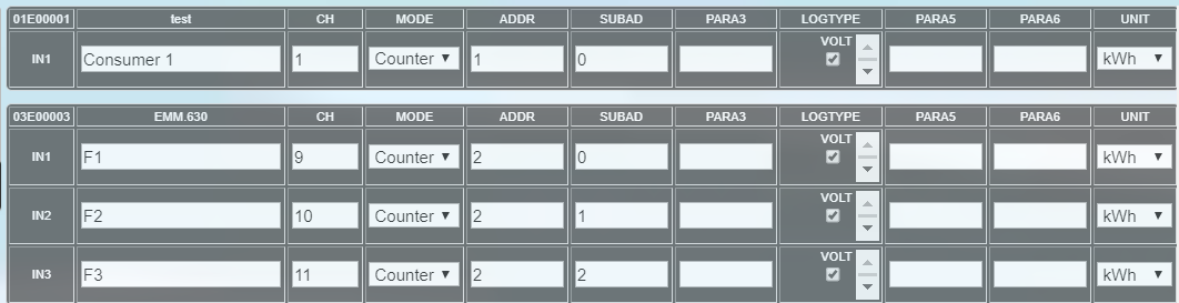
2.3 RF Gateway module communicating on Modbus or on LoRa
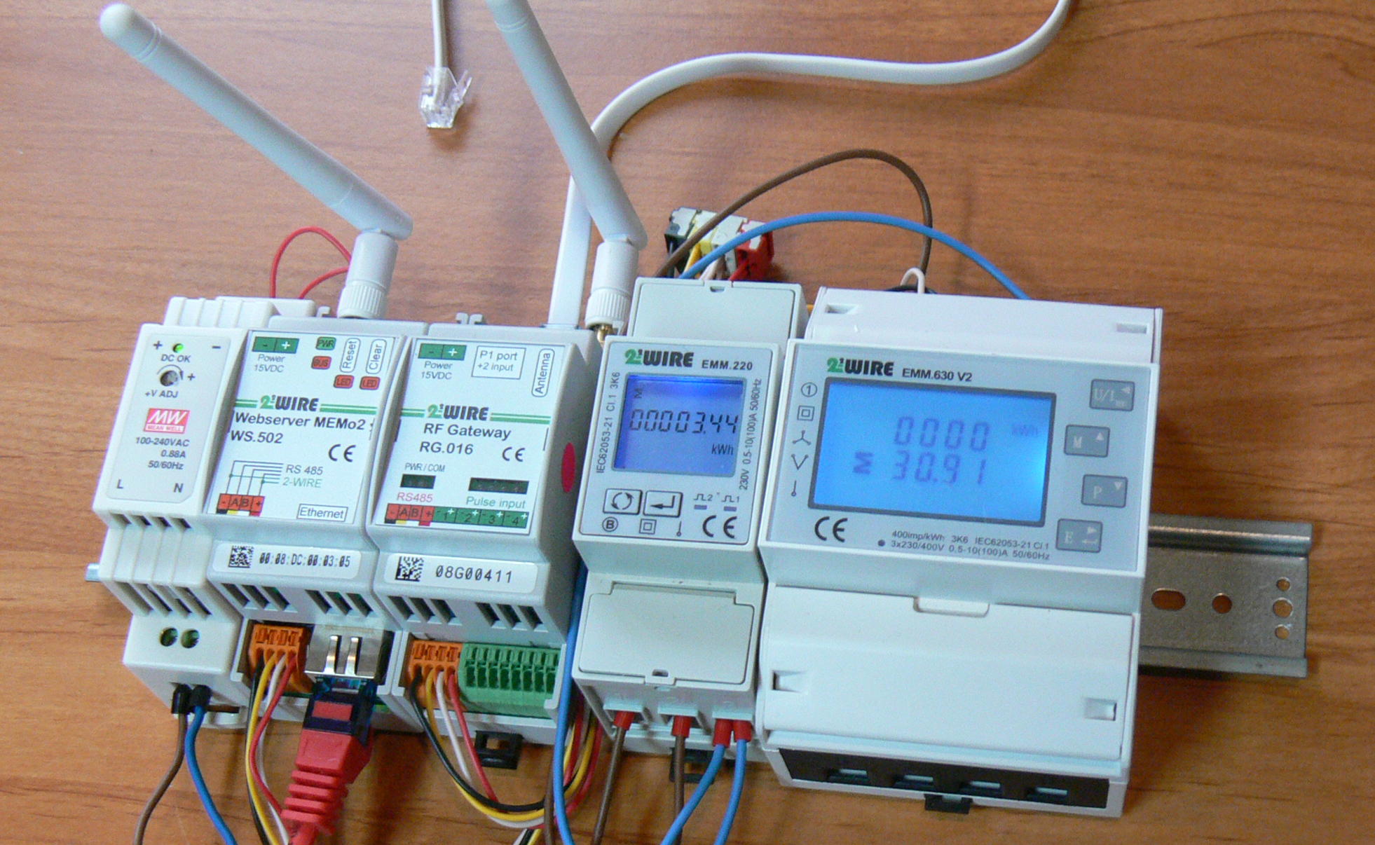
The RF gateway has 4 analog / binary inputs, a serial P1 port connection to the Dutch and Flemish digital meters and possibly 2 extra pulse inputs via the RJ11 plug (option SET P1).
The configuration in the web server is based on the unique serial number printed on the module. When the gateway is via Modbus we enter the address with capital G: example 08G00411, if the gateway is connected via RF we use lowercase g: example 08g00411.
result:
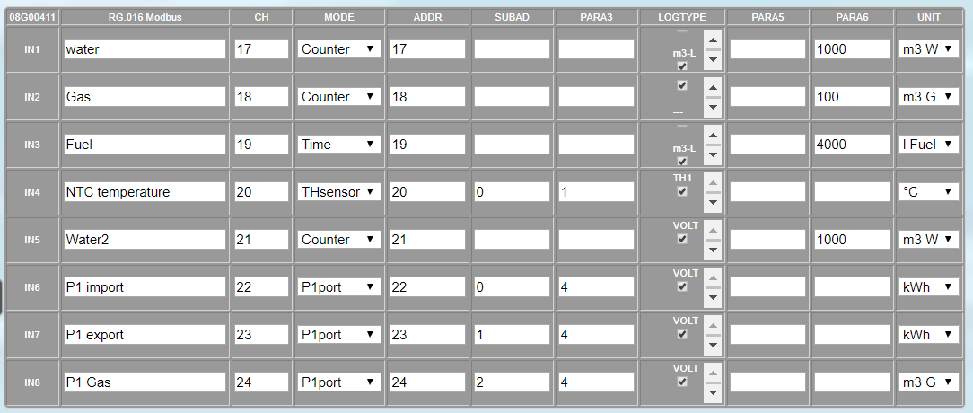
2.3.1 RF gateway communicates on Modbus:
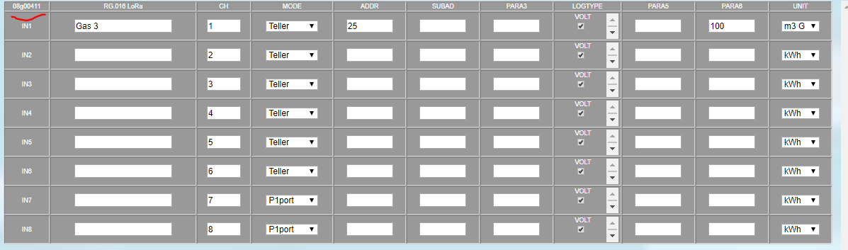
2.3.2 RF Gateway communicates on LoRa
The configuration of a gateway (slave) which is linked via LoRa to the central Memo web server is identical to a gateway linked via Modbus. You must enter the serial number with lowercase g, for example: ’08g00411′ and the RG gateway must still be connected with the central MEM02 web server.
The procedure for joining:
- once the module is created, press send and then “MODULE NOK” appears on the green bar.
- Now tension on the RG. Set the 016 module so that the gateway enters join mode for 1 minute: PWR and COM led flash alternately
- Press the green “MODULE NOK” button in the web server so that “Join 30sec” appears
- Press send
2.4 Energy meters type EMM.xxx on LoRa
The configuration of an energy meter that is connected wirelessly via a “slave” gateway to a Memo server is almost identical to an energy meter connected via Modbus. The only difference: the name of the module is now the serial number of the “slave” gateway ….
With the “TEST” button you can read the signal strength.

2.5 Smartplug type EP.16A on RF
The configuration of a smart plug is done like any RF module: first the serial number (eg 10S00031) and a unique Modbus address are entered, the module is connected. The signal strength can be read with the test button.

2.6 Wireless Energy Counter ECF.08 on RF
The configuration of a wireless energy counter is done like any RF module: first the serial number (eg 08F00011) and a number of unique Modbus addresses are entered, the module is connected. The signal strength can be read with the test button.

3.0 Channels
In “Channels” we provide the layout for the end user. With the “sort” button we can change the order of the energy channels, with “groups” we create directories …