Energy monitor
on Web Server
On the webpage below we post tutorials to explain the configuration and functionalities of the ReMI web server. You can download the extensive manual and abbreviated QS (QuickStart) manual here
1. Collect network settings
Before starting to link the ReMI web server to your local WiFi network, you need the WiFi password .
And then depending on whether you connect manually or automatically via DHCP , you also need a number of IP addresses in the range of your own WiFi network for manual, namely:
- a fixed and free IP address for LoWi3
- IP address subnet mask
- IP Address Gateway
- Port number
To determine the correct addresses you can go to the network settings of your PC and copy them there, or you can use the Windows IP server scanner tool which you can download from our website.
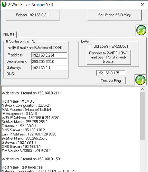
IP server scanner
Once installed you can start server scanner via the shortcut on your PC worksheet. The tool shows the IP address, subnet mask and gateway of your PC at the top left.
Subnet mask (eg 255.255.255.0) and gateway (eg 192.168.0.1) can be taken over, for the DNS address you can take 8.8.8.8. For the fix IP address you take the IP address of your PC (eg. 192.168.0. 234 ) and you change the 4th digit with a number between 2 and 254 and this number ( Ex. 192.168.0. 125 ) you enter above the ‘test via ping’ button. With this button you can test whether this IP address is still available and if not, adjust the fourth number and test again, until you have a free IP address.
For the port number, choose a number between 8000 and 9000, e.g. 8111
In this way all necessary addresses are collected to enter them via the ‘REDIRECT ‘ page in your ReMI web server.
This server scanner tool can also be used to find the IP address of all already configured web servers in your network (LoWi, ReMI, MiLo, MEMo). The two buttons ‘Reboot’ and ‘Set IP’ only work for the MEMo web server.
You can see the summary in the video below:
2. Connect ReMI to your WiFi network.
2.a WiFi access point
The next step is to put ReMI temporarily in “WiFi access point mode”, and then connect your PC to this ‘ReMI WiFi network’ and enter the collected IP addresses and WiFi password into ReMI via the REDIRECT page so that ReMI is linked in your network.
The procedure is as follows: Connect the ReMI server to the P1 port of the digital meter. As soon as your ReMI has started up, the green PWR will light up brightly and then the orange CPM LED will light up and after a few seconds it will go into on/off status. ReMI is now temporarily a WiFi access point.
Remark: If your ReMI module is already connected to your WiFi network and you still want to change these WiFi network settings: disconnect ReMI and then reconnect it to the P1 port and then within 3 seconds and after the first LED flash keep pressing the ReMI switch for about 4-6 seconds until the orange LED lights up continuously. After you release you will get the on/off again to indicate that ReMI is in access point mode.
REDIRECT PAGE
Now that the orange COM LED is flashing, ReMI is temporarily a ‘WiFi access point’ and in the list of WiFi networks on the laptop or tablet you will find the ‘2WIRE-REMI’ network. Select this network. If you are asked for a password: ‘adminREMI’.
A login screen /REDIRECT page will automatically appear in your web browser after 1-2 minutes (or surf to 192.168.4.1 from the ‘2WIRE-LOWI’ network itself).
On this REDIRECT page we can then choose a WiFi network, WiFi password and either enter the collected IP addresses ourselves (see 2.a Manual linking)
or put the ReMI in dhcp mode so that it enters the IP addresses for you (see 2.b Automatic linking via DHCP).
In the video below we have gone through all the steps in full.
TROUBLESHOOT: It is very important that during this one-time configuration, ReMI and the PC and the WiFi router with internet access, are in close proximity and that a stable WiFi connection is available.
If the digital meter is too far away, I occasionally use the P1 adapter cable, because this way I bring ReMI closer to the WiFi router during this process. If it doesn’t work with the PC, try with a laptop or smartphone. If you are not a hero with WiFi networks yourself, ask for help from an acquaintance. If you think you are doing all the steps correctly and that there is something wrong with the module, you can still order a ‘review module ‘.
2.b Manual pairing
You can now enter the collected IP addresses yourself and press save. Afterwards go back to your default network and enter the entered IP address + port number in the web browser to get to the ReMI dashboard.
2.c Auto pairing via DHCP
Enter ‘0.0.0.0’ for IP address, sunetmask, gateway and DNS. The port number is chosen any number between 8000 and 9000 and then press ‘SAVE’. The ReMI is then assigned a fixed IP address from the Router. You can request this address with the IP server scanner
3. ReMI basic functionality
“DASHBOARD” on this page you have the option to select 2 meters and from this you will receive a continuous update of current powers, consumption and moving graphs.
“SETUP” via the ReMI button at the top takes you to the setup screen. Here you can e.g. Verify WiFi signal strength, all values less than -80dBm indicate good WiFi reception. Here you can upgrade the firmware, set energy prices, configure up to 16 log channels, set weeklocks and if-then-else logic. When you make changes, the save button turns red and you need to confirm the change with the password ” adminREMI “.
“DETAILS” you will see all set log channels with meter readings and graphs.
“PRINT” at DETAILS exports data from the charts to Excel.
“TABLE” gives an overview of the last 2 years.
In the video below we go over the different web pages and the P1 port outputs.
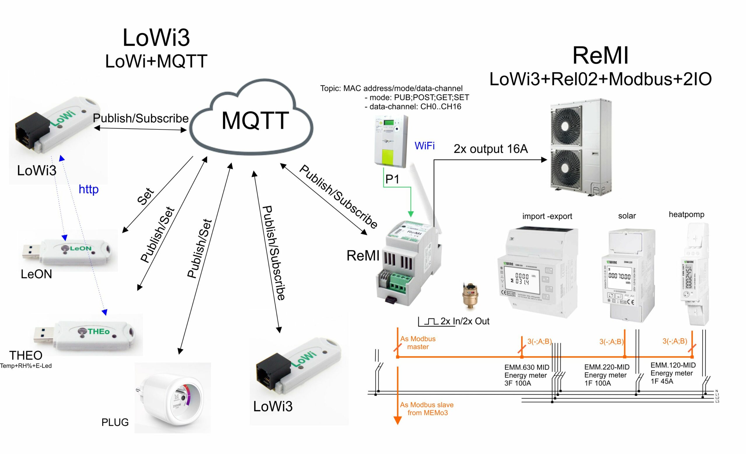
4. MQTT links:
ReMI has the possibility to connect via MQTT with various 2-WIRE web servers and their connected meters (LoWi3, ReMI, MEMo3), as well as with a number of separate WiFi modules (LeON, THEo, Plug) over the internet. The implementation is very simple and the possibilities are enormous. The diagram below provides an overview with a number of links.
To be able to use this extra functionality ‘link over the internet’ you need a license on an MQTT broker. As a private user it is best to subscribe to the MQTT broker from 2-WIRE and this makes MQTT easy to use, as an OEM customer you can use your own MQTT broker.
Note: setting up your own MQTT broker requires some specialized knowledge and is not intended for the average user. It is also not the intention that our technicians provide support and/or training for this, that is too time-consuming and would also distract too much from our own tasks.
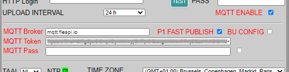
Activate MQTT:
In the ReMI setup page, check the option ‘ MQTT ENABLE ‘ and the input field for MQTT will open. Here you can enter the MQTT broker URL and the MQTT token of your account. Or if you have your own MQTT broker, you can also enter a login and password instead of a token.
Every 2-WIRE module that you want to connect to this ReMI via MQTT will receive the same MQTT account settings. With ReMI and MEMo3 you can enter this via the setup webpage, with LeON, THEo and PLUG you can enter this via the Redirect page during the connection to your WiFi network. see also the manual for MQTT
Publish MQTT Log Channels (Publish):
Once a module is paired with MQTT, it will automatically upload ( publish ) all its log channels to the MQTT broker with every change. LoWi3 and ReMI have up to 16 log channels, MEMo3 has up to 64 log channels, THEo has one log channel,… which are all uploaded ‘live’ with every change.
Read MQTT log channels( Subscribe):
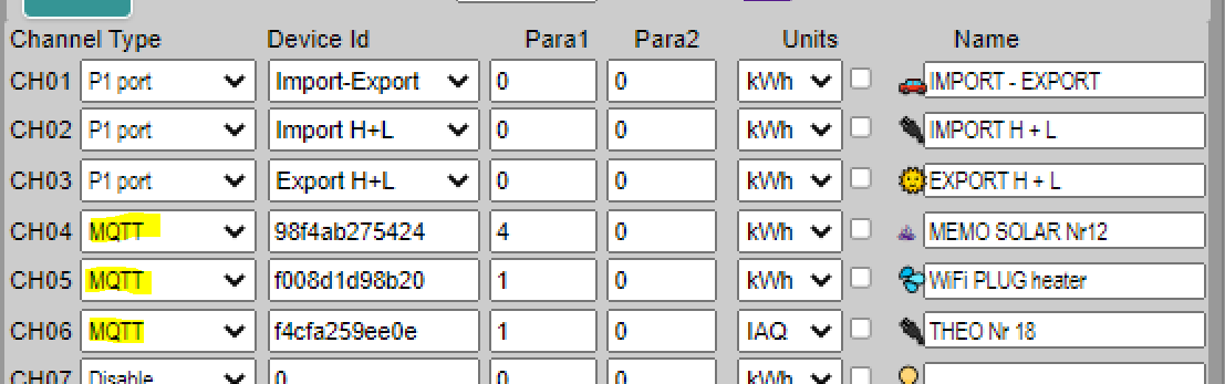
To subscribe to an MQTT log channel, choose MQTT at ‘channel type’.
Under ‘Device id’ comes the MAC address of the linked mode, while ‘Para1’ refers to the desired log channel in that module:
- LeON, THEo , PLUG only have one log channel so enter number ‘1’ here. As unit ‘UNIT’ choose ‘IAQ’ for THEo, ‘kWH’ for WiFi PLUG
- LoWi3 , ReMI have up to 16 log channels, MEMo3 has up to 63 log channels so if you want to read data ( subscribe ) here you enter the desired log channel number along with the correct ‘UNIT’.
At ‘name’ you choose a name that is recognizable to you. No name means no log channel.
In this way you can read data from a module that is installed anywhere in the world.
In the video below we show it briefly or you can also read it in the MQTT manual.
5. ReMI, smart energy switch :
In addition to the 16 log channels, ReMi also has 4 week clocks and 4 relay outputs to switch on time, power, peak consumption, temperature, …. These 4 outputs each have their own channel number:
- Kanaal 17: relais contact 1
- Kanaal 18: relaiscontact 2
- Kanaal 19: solid state uitgang 1
- Kanaal 20: solid state uitgang 2
With the “IF-THEN-ELSE and “AND and OR” logic you can smartly switch the 4 outputs above, or MQTT plugs.
In the video below we show how we switch a boiler connected to relay contact 1 ( Channel 17) to injection and to weekly clock.
And in a second example, a smart plug is switched off when peak consumption is too high.
Let’s explain the example in words:
example 1: Switching on measured power:
With EXPORT H the injection is measured,
IF 1500 Watt injection is reached and as long as it does not drop more than 1200 Watt,
OR when the CLOCK1 becomes active
THEN after a 2 minute delay, the relay 17 will follow the logic (FOLLOW: ON if logic TRUE, OFF if logic FALSE) and switch on. Once the logic goes false the relay will remain ON for another 10′ before tripping.
example 2: Switching to measured quarter-hour power:
With “IMPORT H” and “Peak Pwr” the quarter-hour power is measured at 5′ and 10′. If at one of these 2 times the quarter hour power is exceeded, the logic is true and the linked output is switched off. At 15′ the quarter-hour counter is reset to zero and the logic is therefore false. The output follows the INVERSE logic and is thus turned on again.

In the LOGIC OVERRULE column you can control the output manually with the on and off button, or have it controlled automatically with the logic button. Green means output is off, red means output is on.
6. ReMI Applications :
With the 4 relay contacts you can connect to the ‘smart energy’ input of your heat pump or heat pump boiler, or you can control the boiler, storage heating, charging station, … according to peak consumption or energy rate.
With the MQTT coupled plugs you can monitor individual appliances (pond pump, household appliances, …) and even smartly switch to weekly clock and injection, for example.
You can use multiple ReMis in your installation and link them together via MQTT, or link them by connecting 2 or 3 ReMIs with the P1 hub to the same digital meter.
The aim: to gain insight into (partial) consumption in order to make the right investment, or to increase your own consumption of solar energy and thus reduce your energy bill, or to smooth out your peak consumption and thus pay less grid fees.